Description:
The Intel® Edison is an ultra small computing platform that will change the way you look at embedded electronics. Each Edison is packed with a huge amount of tech goodies into a tiny package while still providing the same robust strength of your go-to single board computer. Powered by the Intel® Atom™ SoC dual-core CPU and including an integrated WiFi, Bluetooth LE, and a 70-pin connector to attach a veritable slew of shield-like “Blocks” which can be stacked on top of each other. It’s no wonder how this little guy is lowering the barrier of entry on the world of electronics!
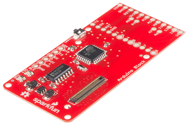
Piggyback an Arduino onto your Edison with the Arduino Block. This board features the same ATmega328P you’ll find on Arduino Uno’s, Pro’s, and Pro Mini’s. The 8-bit microcontroller workhorse is connected to the Edison via a selectable UART, so your Edison can interact with the Arduino over a serial interface.
The GPIO pins of the Arduino are all broken out to the familiar Pro Mini form factor. You can jump wires off of them to control LEDs, motors, or sensors. Or connect it straight up to a Pro Mini shield.
If you are looking to add a little more stability to your Intel® Edison stack, check out this Hardware Pack. It will provide you with increased mechanical strength for stacking Blocks on your Edison!
Introduction
The Arduino Block for Edison provides the Intel® Edison with a direct, serial link to an Arduino-compatible ATmega328 microprocessor.
 ?
?
Why would you need an Arduino connected to your Edison? Isn’t it powerful enough to handle anything that may be thrown at it? That’s the problem ? it’s almost too powerful. Because it’s running an operating system, it’s incapable of real-time processing ? the bread-and-butter of smaller microcontrollers like the ATmega328. Components which require precise timing ? like WS2812 LEDs or servo motors ? may be incompatible with the Edison as it can’t reliably generate clock signals.
The Arduino block allows the Edison to offload those lower-level hardware tasks. Additional to that, if you’ve already written Arduino code for an external component, you don’t have to port that code to the Edison ? just run it on an Arduino block!
Board Overview
 ?
?
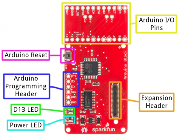
- Expansion Header ? The 70-pin Expansion header breaks out the functionality of the Intel Edison. This header also passes signals and power throughout the stack. These function much like an Arduino Shield.
- Arduino I/O Pins ? All of the Arduino’s I/O pins are broken out to a pair of headers (plus a couple in between). This header footprint exactly matches that of the Arduino Pro Mini ? if you have any Mini shields they should mate exactly to this header.
- Arduino Programming Header ? The standard 6-pin FTDI header is used to program the Arduino’s serial bootloader. Plug a 3.3V FTDI Basic in to program your Arduino.
- D13 LED ? Every good Arduino needs an LED! This small, green LED is tied to the Arduino’s pin 13. Great for blinking “Hello, world” or debugging.
- Power LED ? The Arduino block has an on-board 3.3V regulator, and this LED is tied to the output of that regulator.
- Arduino Reset Button ? This reset button is tied to the Arduino’s reset line. It will only reset the Arduino; it has no effect on the Edison.
The Arduino block pairs the ATmega328 to your Edison via one of two UARTs. The board defaults to connecting the Arduino to Edison via UART1. Jumpers (see more below) allow you to select UART2, if your application requires. Take care using UART2, though, it’s default utility is for console access to the Edison.
The Arduino Block has an on-board 3.3V voltage regulator, which takes its input from the Edison’s VSYS bus. Since the Arduino is running at 3.3V, its clock speed is limited to 8MHz.
If you want to take a closer look at the schematic, download the PDF here.
Jumpers
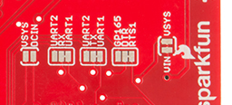
On the back-side of the Arduino block, there are a handful of jumpers, which lend extra utility to the board.
? ?
?
Three two-way jumpers ? for RX, TX, and DTR ? allow you to select between UART1 (default) and UART2. To switch these jumpers, grab a hobby knife, cut the default traces, and drop a solder blob between the middle pad and outer pad of your choice.
The jumper labeled VIN/VSYS allows you to remove the VSYS line from powering the Arduino block. This is handy if you need to isolate the Arduino block’s power source from the Edison. In this case, you’ll need to supply power (3.3-12V) externally via the “VIN” pin.
Using the Arduino Block
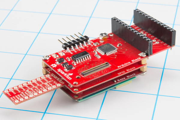
To use the Arduino Block, attach it to either an Edison or add it to a stack of other SparkFun Block’s.
 ?
?
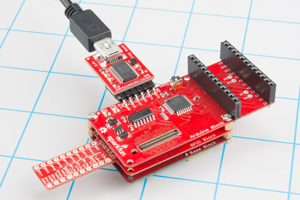
Arduino block stacked on top of a GPIO Block and a Base Block.
In order to supply power to your Edison, you’ll need at least one additon Block in your stack. You can use a Base Block or Battery Block, for example.
Programming the Arduino
The Arduino on the Arduino Block can be programmed while it’s either on or off the Edison. Depending on your application, though, it’s recommended that you load code on the Arduino while it’s disconnected from your Edison stack, before adding it to the rest of the system.
If you’ve ever uploaded an Arduino sketch to an Arduino Pro or Pro Mini, you’re already familiar with uploading code to the Arduino block. Connect a 3.3V FTDI Basic to the 6-pin FTDI header on the board.
 ?
?
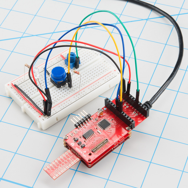
Using a 3.3V FTDI Basic to program the Arduino on the Arduino Block.
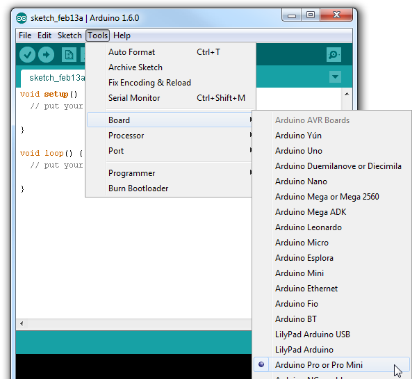
In Arduino (the non-Edison version of Arduino!), select “Arduino Pro or Pro Mini 3.3V/8MHz” from the Tools > Board menu. If you’re using the latest release of Arduino (1.6 or later), first select Arduino Pro or Pro Mini from the “Board” menu.
 ?
?
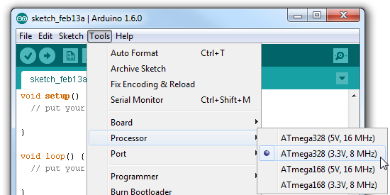
Then select ATmega328 (3.3V, 8MHz) from the “Processor” menu.
 ?
?
Then upload away!
Using the Arduino Pins
The Arduino’s I/O pins are all broken out to a pair of headers. These headers match up exactly to the Arduino Pro Mini. If you have any shields or piggyback boards for a Pro Mini, it should work seamlessly with the Arduino Block.
You can solder headers, wires, or any other connectors to these pins.
 ?
?
If you’re soldering headers to the pins, take extra care deciding which side to solder to. Depending on the rest of your Edison stackup, those headers might get in the way of connectors on other boards (the USB connectors on the Base and Console Blocks, in particular).
Connecting the Edison to the Arduino
The Arduino Block connects the Arduino to the Edison through a serial (UART) connection. Jumpers on the back of the board allow you select which of the Edison’s two UARTs mate with the Arduino. Unless you can’t avoid it, we recommend leaving the jumpers in the default configuration ? the Edison’s UART2 is usually devoted to console access.
To program the Edison to control and interact with the Arduino, you’ll need to use the UART to establish a communication protocol between the devices. See the next section for an easy example of UART communication between Arduino and Edison.
Controlling the Arduino Block with Firmata
Firmata is an established protocol popular within the Arduino realm for applications that require a separate machine (usually a computer) to control the Arduino. It’s a serial-based protocol that uses defined messages to set digital pins, read analog pins, and do everything else you’re used to with Arduino.
Firmata is so useful, the standard Arduino IDE even ships with the Firmata library. Here’s an example of how an Edison can be used to control and interact with an Arduino running Firmata.
Upload StandardFirmata to the Arduino
Before uploading any code to the Edison, let’s load something into the Arduino. Once the Firmata code is running on your Arduino, you may never have to upload code to it again.
Using the standard Arduino IDE (i.e. not the IDE built for Edison), load up the “StandardFirmata” sketch by going to File > Examples > Firmata > StandardFirmata. If you have the Codebender addon installed, you can use the embed below to upload the code to your Arduino Block.
With the Firmata firmware uploaded, you can disconnect the FTDI Basic, and connect the Arduino Block to your Edison stack.
Edison Firmata for Arduino Client
The harder part of this equation is writing something that executes on the Edison which interacts with our Firmata-running Arduino. There are tons of great client examples in the Firmata GitHub profile, but nothing quite built for the Edison.
Riffing on the Firmata Processing example, we wrote this sketch to enact an Edison Firmata client.
Arduino version alert! This Arduino sketch is intended to run on the Edison. You'll need to download the Edison Arduino IDE, and use that to upload this code to your Edison. For more help programming the Edison in Arduino, check out our Getting Started with Edison tutorial.
Here’s the sketch. Copy/paste from below, or grab the latest version from this Gist:
After uploading that sketch to your Edison, your Arduino Block should begin blinking the D13 pin. You can also open up the Serial Monitor to see what values your Arduino Block is reading in on D4 and A0.
This serves as a simple Firmata client for the Edison, but it should be easily expandable. Try using any of these functions (defined in lower portions of the sketch) to add more features to your Edison Firmata Client:
- firmata_pinMode([pin], [mode]) ? As with any Arduino sketch, setting the pin’s mode is critical. Firmata requires an extra bit of information. Use any Arduino pin for the [pin] variable. For the [mode] variable use either MODE_INPUT, MODE_OUTPUT, MODE_ANALOG, MODE_PWM, MODE_SERVO, or MODE_SHIFT.
- firmata_digitalRead([pin]) ? Read in the digital value of a pin. This function will return a value between 0 and 1. That pin should be set as MODE_INPUT before calling this function.
- firmata_analogRead([pin]) ? Read in the value of an anlog pin. This function will return a value between 0 and 1023. The pins should be set as MODE_ANALOG before being read.
- firmata_digitalWrite([pin], [value]) ? Write a digital pin either HIGH or LOW. The pin should be set as MODE_OUTPUT before calling the function.
- firmata_analogWrite([pin], [value]) ? Write an analog-output pin to a value between 0 and 255. The pin must be PWM-capable ? that means either pin 3, 5, 6, 9, 10, or 11. And it should be configured as a MODE_PWM before hand.
- firmata_servoWrite([pin], [value]) ?Set a pin to output a servo signal. The value here is an angle between 0 and whatever the high-end angle of your servo is. Remember to set the pin to MODE_SERVO before calling this function!